: Dwelling Automation – join 8 channel relay + Raspberry Pi
Warning: Undefined variable $post_id in /home/webpages/lima-city/booktips/wordpress_de-2022-03-17-33f52d/wp-content/themes/fast-press/single.php on line 26
The best way to , Find out how to: House Automation - join 8 channel relay + Raspberry Pi , , Z2B67hybdAA , https://www.youtube.com/watch?v=Z2B67hybdAA , https://i.ytimg.com/vi/Z2B67hybdAA/hqdefault.jpg , 413820 , 5.00 , If you're planning to use a relay in your Raspberry Pi mission it is best to check this video out. See earlier movies: ... , 1377392492 , 2013-08-25 03:01:32 , 00:03:44 , UCuwFJkahErfhbroefg12lzA , skiwithpete , 907 , , [vid_tags] , https://www.youtubepp.com/watch?v=Z2B67hybdAA , [ad_2] , [ad_1] , https://www.youtube.com/watch?v=Z2B67hybdAA, #Residence #Automation #join #channel #relay #Raspberry [publish_date]
#House #Automation #join #channel #relay #Raspberry
If you happen to're planning to make use of a relay in your Raspberry Pi project you need to test this video out. See earlier movies: ...
Quelle: [source_domain]
Is there a way to add a manual switch to each relay to bypass the pi? Basically adding a manual feature to turn on/off each relay…
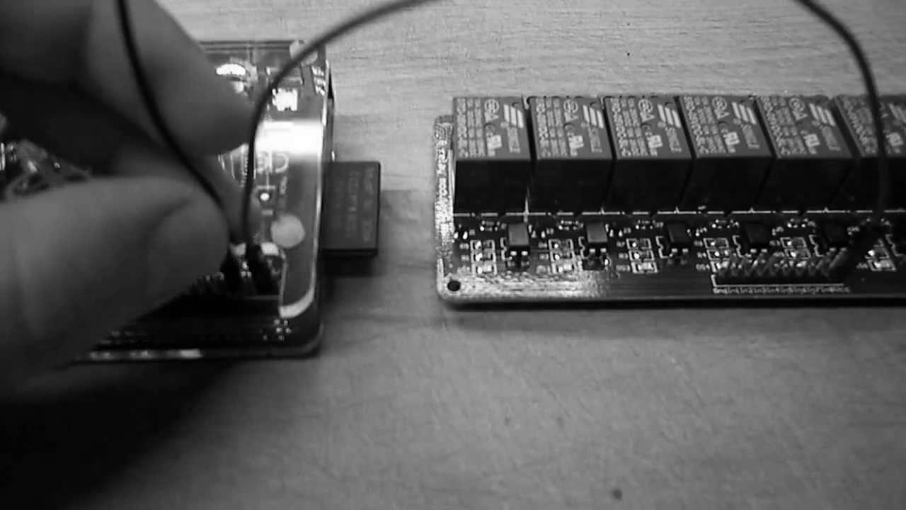
Thus – as this appears to be – an 8-way 12vDC RELAY board – with opto-couplers on all inputs.
I take it (also) that your "Raspberry Pi" – is only outputting a 5vDC power source..
You are attempting (in this video) to tell everyone here, that the 5vDC (your little device outputs) is good enough to provide enough power for all 8 of those 12vDC relay coil circuits, even if these 12vDC coils – are all powered on (as occurs at some stage of the relay ops).
I would assume that you have zero idea, what the opto-couplers are there for, as their primary function is to increase the 5vDC signal outputs from your PI – to operate the 12vDC relay coils.
Thus – you have to have a 12vDC supply (ready) for the relay coils, and that then allows for these 5vDC signal outputs from your PI device – to control the 12vDC feed to each relay – when controlled via the 8 opto-couplers (when a signal arrives from the various 5vDC PI signals – all of which ONLY have 5vDC signals – that are boosted via the "on-board" opto-coupler circuitry.
It is these opto-coupler circuits themselves, that allow the 12vDC to operate the 12vDC relay coils, as they are designed to "electronically" switch the 12vDC supply (to allow each relay coil to get enough voltage & thus working current – off the 12vDC) when your little device can only supply 5vDC signals.
An external 12vDC supply is required to be powered ON at all times that you have the board connected to your PI, thus you also need to switch it on & off, (or have that always on) before any of your PI's 5vDC signals will operate the opto-coupler circuits, to electronically control the relay coil circuits.
To thus allow the 8 "signal controlled" opto-couplers to switch that 5vDC signal – via the 12vDC feed which in turn switches the coils of the 12vDC relays – that each relay those opto-couplers control,
You need to optically isolate the 12vDC supply feed, from your PI's 5vDC signals
The relays thus are switched optically from just 5vDC (when your 5vDC PI sends a signal via one of the 8 outputs – all of which ONLY have a 5vDC signal feed, coming from the PI master unit).
As the relays themselves require 12vDC – the 5vDC signals coming from your PI will NEVER be sufficient to power-on 1 relay coil – let alone all 8 of the relay coils – unless they are BOOSTED by the opto-coupler booster circuits.
Only by way of the opto-coupler circuits, can the 5vDC – switch the 12vDC into their respective 12v Relay coils – which then allows your tiny 5vDC signals to be keeping the relays ON – as this is achieved from the 12vDC supply – powering the relays via the opto-coupler circuit/s.
THE 230vAC (lighting mains power) on the relay contacts themselves – that is (ALSO) isolated from BOTH the 12v relay coil circuits, as well as double isolated from the 5vDC PI signal outputs, by way of the relays themselves AND by way of the isolation features – of those 8 opto-couplers.
p.s.
NEVER FEED any relay's N/O terminals – with 230v AC mains, as these SPDT contacts are designed to ONLY have the commons looped across live mains.
The relays then switch the mains via either NO – or the NC contacts.
Thus one can have a small RED / GREEN illumination panel at or beside the output contacts, such that (at a glance) one can instantly tell if a relay is powered on – or not.
By inserting the mains – into ONLY the NO contact terminals and looping from there.
You can NEVER get switch functions indicated on a control panel – showing the aspects of each relay.
Why?
Because the NC contacts can NOT get power from the NO contact – as the common contact disconnects from the NO before closing the NC (& visa versa).
..
Now lets get it straight shall we.
Your PI is 5vDC (only) and outputs low power (low current) 5vDC signals
The relays are all 12vDC (meaning that they have higher current consumption 12vDC coils)
It's the relay contacts – that switch the 230v AC Mains.
The 5vDC PI does NOT directly switch the 12vDC relay coils (that's what the 5vDCto12v DC opto-couplers are for)
&
The PI also does NOT switch directly – any of the 230v AC Mains circuits – (that's what all 8 relay contacts are for via the NO & NC contacts) .
By connecting JUST your 5vDC PI directly to the 12vDC relay board – to directly control all 8 relays
You seriously run the risk of destroying your tiny PI's 5vDC output signal circuits, as these ARE NOT DESIGNED – to power 12vDC Relay coils.
You can get away with direct driving "relays" from the PI – when using one (or two) 5vDC relays only.
Never attempt to circumvent the opto-couplers by selecting the JUMP circuit jumper – as that LINK is there for 12vDC signals.
Not for direct driving 12vDC relay coils, from the tiny PI's 5vDC low-current signal outputs.
Also of note.
NEVER EVER loop the 230v AC Mains – by using the NO contact terminals of any relay.
The COMMON terminal is best for that – as inside the relay – the common terminal circuit is better protected from the coil circuit.
When the NO contact closes, there's usually a load on that circuit, such that the risk of an internal spark-over is lessened.
Also – if one needs BOTH a normally open AND a normally closed contact – for any ONE circuit controlled by each relay – by feeding the live AC in via the NO contact – you defeat the need for the NC contact (as it will NEVER see the live AC mains)
.
The additional reason for center feeding (via the Common terminal) the 230vAC mains is this, when any relay FAILS to operate – there is the option of having a Normally Closed "indicator light" connected.
Thus one can instantly see – which relay is powered ON – & which is faulty (if it should be on)
You can also see which has blown internally – if all indicators for that relay are both on (or both off)
Sparkies know a little more (about electrical circuits and their design characteristics) than your everyday kit-basher – as that's been our lively-hoods, for most of our working lives.
is it possible to connect the GP10 direct to a mosfet like IRF840PBF ? or i need also relay like the one you showed to turn on and off the gate on the mosfet IRF840PBF ?
If 2 or 3 or more relays to be kept staying on, would the relay board drawing to much current than the raspberry pi can handle? Thanks.
I thought I blow my boards up only to realize, they were high and needed to pull them down via negative. Now i can proceed with my project all thanks to your helpful video
The wiring diagram with relay and how did you connect thee output
Yes!
Hy i have a switch tah conected to 15 lamp. Am i able to use relay to switch 15 lamp in one channel. I don't know the specifications of lamps that im use.
If internet connection fail but i want to use my 8 chanel Arduino to on off light without internet plz send me wiring diagram for this use
can I use xlights or what show setup can I use I'm wanting a pixel and relay Christmas show so need to use a setup to run both
What is the switching capacity of that relay?
Hi! can you please tell me what is the maximum number of relays that can be operated with 1 rpi3.
Thanks for the nice videos on this. Really helping me out, and well explained.
Thanks
Can you give some rough dimensions of the 8 channel relay please?
how can you make the relay be constantly sending power when it itself receives power?
I've seen some info that suggests a resistor betweent he GPIO and the relay. Is that necessary or not in your opinion?
please show the actual coding to set the gpio as needed. thanks
can you guide more further about the program to operate these relays.
My automated home:
https://www.youtube.com/watch?v=6jnO74Hd3fE
How does the relay itself wire to something? I have a 4 channel relay I am trying to connect to my 24v sprinkler power line. The sprinkler cable has 3 wires. How do I connect all 3 wires?
Beautiful job! Thanks for sharing.
Howdy, Why did you set the jumper to JD-VCC – VCC?
How did you connect power to the motion detector?
what you guys use to remote control into this unit and how is it done?please. zz
will this communicate with an app?
Hi, i will connect the 8relay board to my rpi2, basically to control lights. Do you have any diagram showing the high voltage connections from the relays to the lights?
thanks
Could you tell me what camera are you using to record this? Its image stabilization is astonishing.